Trench excavation represents one of the most hazardous operations in civil engineering and underground utility construction. One cubic meter of excavated soil weighs between 1.5 and 2.0 metric tons—a sudden sidewall collapse exerts impact force comparable to an automobile dropping directly onto trench workers.
Importantly, trench boxes (trench shields) are non-cast ground support safety systems designed to withstand lateral earth pressure and provide a secure safety chamber for pipe laying and utility workers.
Selecting the right equipment is only half the battle. Proper field execution directly dictates whether a project runs efficiently or faces catastrophic box jamming and equipment downtime.
This practical field guide provides actionable standards for jobsite crews, covering ground assembly protocol and high-strength pin locking, the critical “Inverted A-Frame” anti-jamming fine-adjustment technique for struts, proper excavator pressing points with intermediate pipe pressing strictly prohibited, the standardized 50 cm incremental extraction and backfill compaction cycle, and confined space safety protocols including the 7.5 m ladder egress rule, positive-pressure ventilation and spoil setback, supplemented by real-world field snapshots of three typical overseas working conditions in Georgia, Malaysia and New Zealand.
Modular Trench Shield Anatomy & Core Components
A certified trench shield functions as a passive protective system engineered to resist active lateral earth pressure along with surcharge loads from heavy plant machinery and adjacent traffic.
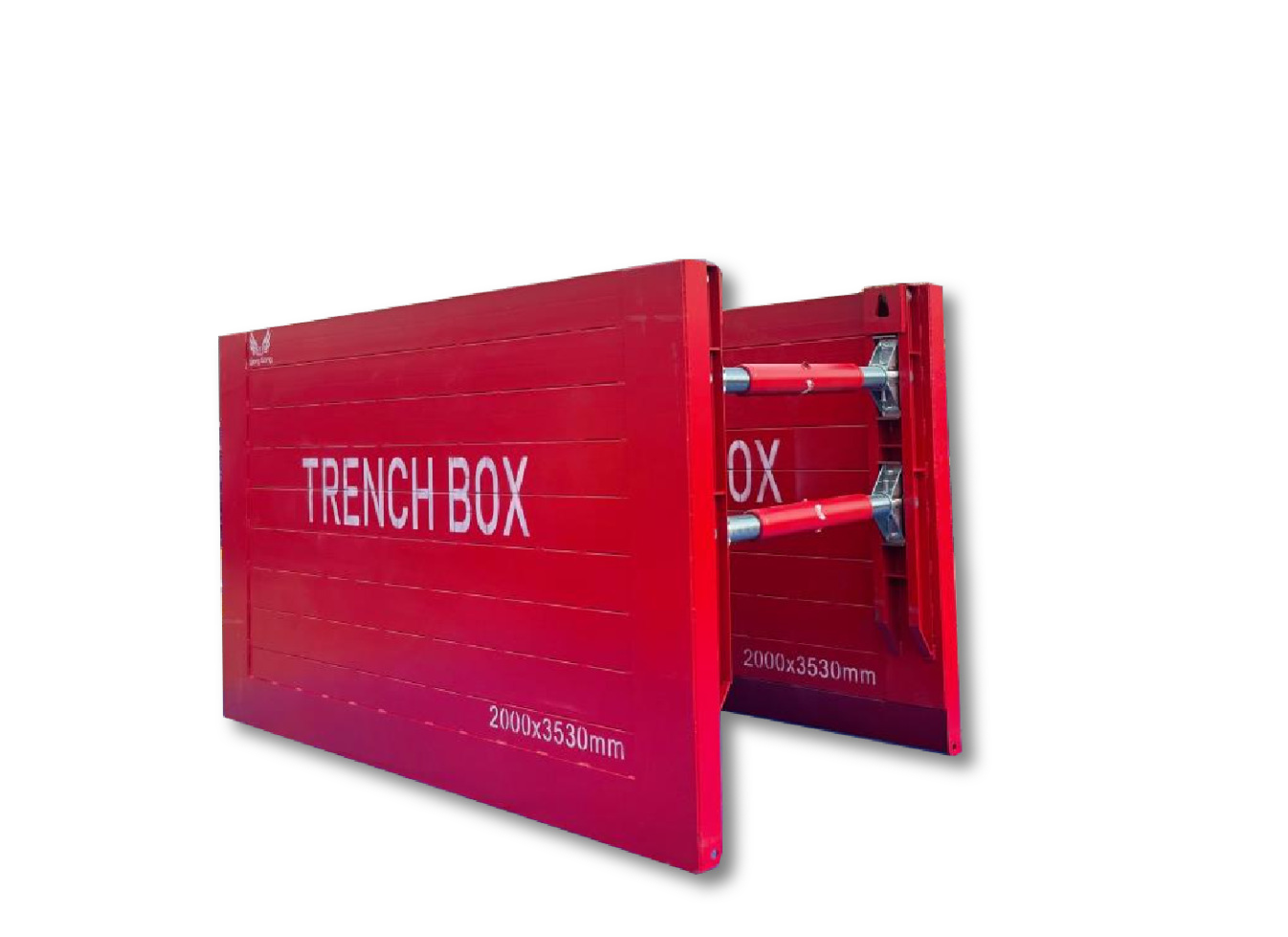
Core Structural Components:
Shield Panels (Side Walls): Fabricated from high-yield structural steel with reinforced corner posts, heavy-duty excavator pushing beams along the top edge, and cutting knives (knife edges) along the bottom edge;
Adjustable Spindles / Struts: Telescopic or threaded strut assemblies that adjust box working width, connected via flexible socket housings to allow minor angular pivoting and dynamic buffering;
Modular Extension Pipes: Standardized spacers inserted into strut assemblies to extend clear working widths across diverse pipe diameters;
High-Tensile Connection Pins & Safety Clips: Solid high-tensile connection pins secured with spring retaining clips (R-clips) to lock struts and extension pipes firmly together. Never substitute with rebar or untreated bolts;
Stacking Connectors: Specialized alignment hardware used to securely couple a top extension box onto a base box when trench depths exceed single-panel heights.
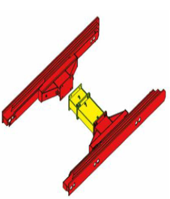
Standard Assembly, Sinking & Extraction Protocols
Step 1: Flat Ground Assembly & Positive Pin Locking
1. Prepare Flat Ground: Place the first panel flat on firm, level ground with socket rails facing upward;
2. Install Strut Heads: Slide strut heads into panel sockets, insert high-tensile locking pins, and secure each pin with an R-clip;
3. Mount Strut Bodies: Connect strut bodies/spindles to the heads, insert locking pins, and secure retaining clips;
4. Align Second Panel: Rig the second panel with a certified four-leg lifting chain, hoist and align carefully with strut sockets, then insert all locking pins and safety clips;
5. Four-Point Hoisting: Once all pins are inspected and locked, lift the assembled box vertically using four-point rigging.
Step 2: The Pro Secret—”Inverted A-Frame” Spindle Adjustment (Preventing Costly Jams)
One of the most expensive field errors is adjusting top and bottom struts to identical, parallel widths. In cohesive clays or moist sands, parallel boxes experience severe sidewall friction after settling, frequently trapping the shield in the ground and causing broken rigging or excavator tipping.
Anti-Jamming Standard:
Adjustment Rule: When adjusting spindles on the ground, set the bottom strut width 30 to 50 mm wider than the top struts;
Mechanical Principle: This creates an “Inverted A-Frame” (trapezoidal) cross-section. As the box sinks, the wider bottom cutting shoe cuts a trench slightly wider than the upper panel profile;
Field Benefit: During extraction, once the box is lifted a few centimeters, the upper panels immediately pull away from soil walls, eliminating lateral friction and protecting lifting equipment.
Step 3: Trench Excavation & Box Placement Methods
Two primary installation methods are available for trench box deployment.
The Place & Adjust Method (Pre-Dig & Set) applies to cohesive, self-supporting stable soil for shallow trenching up to 2.5 m: excavate the trench vertically to target depth, hoist the assembled trench box using four certified chains and lower it to the trench bottom, verify alignment, then proceed safely with pipe bedding inside the shield.
The Cut & Lower Method (Dig & Push Sinking) is suitable for loose sands, soft clay and unstable ground for deep trenching over 2.5 m: first excavate an initial 1.0 m guide trench and place the box, excavate soil from inside the box and below the cutting shoes, use the excavator bucket to gently press the reinforced four-corner posts (300–500 mm per side), and repeat the “dig inside → push corner posts” cycle until the target grade is reached.
Step 4: Post-Pipe-Laying “Incremental Extraction & Backfill” Cycle
Never backfill a trench completely to ground level before attempting to pull the trench box! Doing so severely overloads the excavator and compromises pipe joints.
The 50 cm Incremental Cycle Standard:
1. Complete pipe jointing and place aggregate bedding up to 50 cm inside the shield;
2. Mechanically compact bedding material within the shield;
3. Rig the excavator to top lifting points and raise the box smoothly by no more than 50 cm;
4. Repeat “Backfill 50 cm → Compact → Lift 50 cm” until the box clears ground level;
5. Spindle Pivot Limit: Ensure spindle angular deviation does not exceed ± 8° during incremental lifts to protect socket housings.
Four Critical Jobsite Mistakes to Avoid
| Common Field Error | Structural & Safety Consequence | Correct Operational Practice |
| Excavator pushes directly on middle extension pipes | Severe pipe bending buckling; sheared pins; ruined strut assemblies | Only press on reinforced four-corner posts or dedicated pushing beams. |
| Substituting rebar or standard bolts for certified pins | Shear failure under lateral soil load; catastrophic panel detachment | Always use OEM high-tensile solid steel pins with spring R-clips. |
| Setting top and bottom struts parallel | Massive soil adhesion locking the box underground; broken rigging | Apply the Inverted A-Frame rule (bottom struts 30–50 mm wider). |
| Backfilling the entire trench before pulling the box | Excavator boom overloading; pipe displacement; structural damage | Follow the 50 cm incremental backfill, compact, and pull cycle. |
Confined Space & Trench Crew Safety Rules
1. Safe Egress (Ladder & Stair Tower Positioning):
- OSHA and international standards mandate that when trench depth exceeds 1.2 m, workers must have a ladder or egress point within 7.5 m (25 ft) of lateral travel;
- Ladders must extend at least 0.9 m (3 ft) above ground or shield top and be securely tied off.
2. Spoil Pile & Surface Setback:
- Excavated spoil piles and heavy equipment must maintain a minimum setback of 1.0 to 1.5 m from the trench edge to prevent overload collapse and roll-in hazards;
- No personnel are permitted inside the shield during hoisting, repositioning, or machine sinking.
3. Atmospheric Testing & Ventilation:
- In deep excavations or near utility pipelines, conduct gas testing (H2S, CO, combustible gases, and O2 levels 19.5%–23.5%) before entry;
- Deploy positive-pressure ventilation blowers with flexible ducts to ensure fresh air circulation.
Global Field Snapshots: Three Real-World Applications
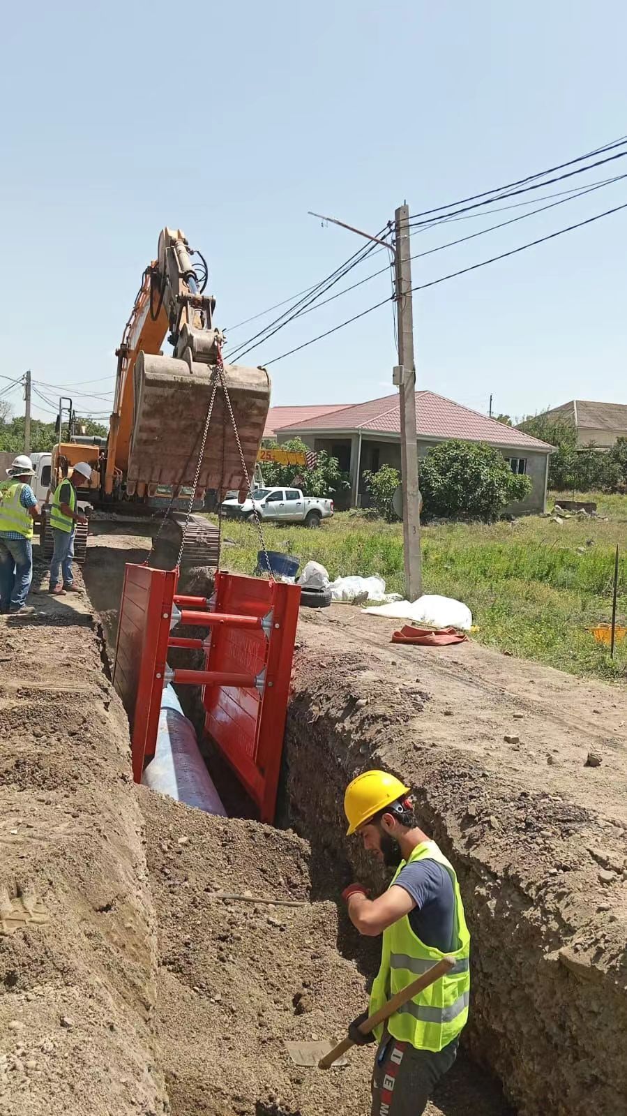
Narrow Village Roads & Sensitive Foundations (Georgia Water Pipeline)
Application: Long-distance potable water transmission along existing rural corridors;
Challenge: Trench alignment adjacent to residential foundations and utility poles with zero space for open battering;
Solution: High-rigidity steel trench boxes placed vertically, minimizing excavation footprint and preventing soil displacement near adjacent structures.
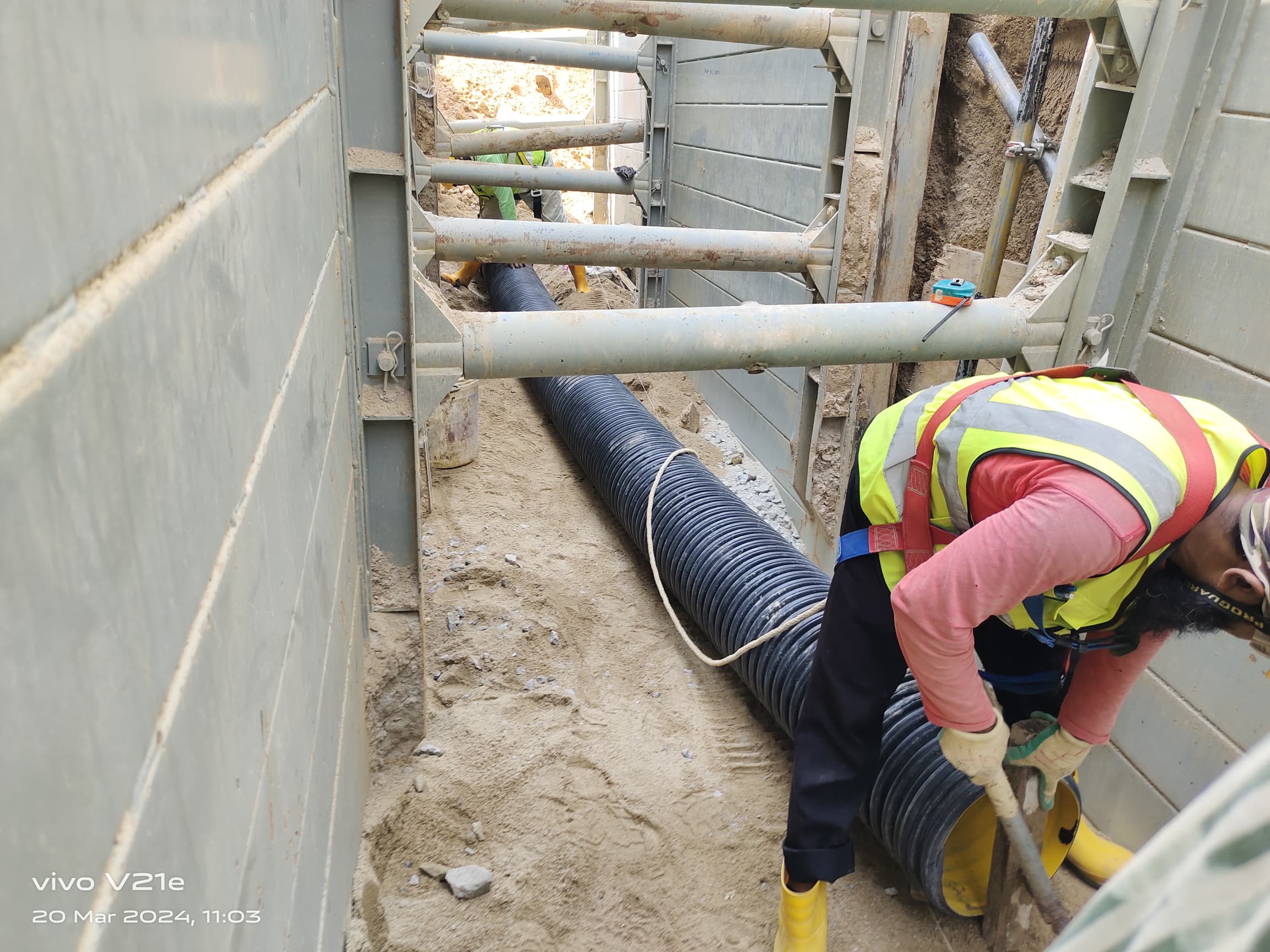
Saturated Ground & Multi-Box Continuous Train (Malaysia Sewer Main)
Application: Deep municipal trunk sewer construction;
Challenge: High groundwater table and loose, saturated soil requiring extended worker protection during large-diameter HDPE pipe installation;
Solution: Multiple steel trench boxes coupled in a continuous linear train, creating an extended protected working gallery with dedicated ladder access and ventilation.
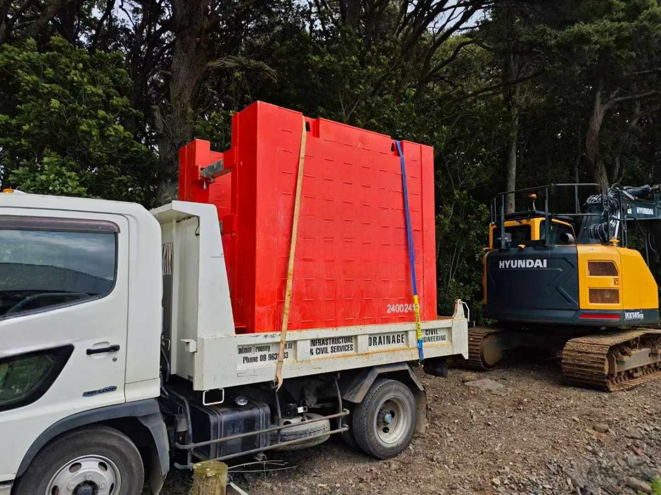
Rapid Municipal Transport & Compact Installation (New Zealand Manhole Project)
Application: Urban drainage inspection chambers and valve pits;
Challenge: Dispersed urban locations where heavy transport permits and traffic disruption create high costs;
Solution: Four-sided Manhole Boxes transported efficiently on standard utility trucks and installed swiftly with mid-sized excavators.
Trench Shoring System Quick-Selection Matrix
| Ground & Site Conditions | Trench Depth Range | Recommended Shoring System | Standard Installation Method | Key Application Benefits |
| Cohesive Clay / Narrow Road / Shallow Pipe | <2.4 m | Single Steel Base Box | Place & Adjust (Pre-dig & lower) | Fast cycle time; minimal setup |
| Loose Sand / High Water Table / Mainlines | 2.4 m to 4.0m | Continuous Train / Base + Top Stack | Cut & Lower (Incremental sinking) | Continuous safety gallery; deep reach |
| Urban Chambers / Valve Pits / Spot Pits | 2.0 m to 3.5 m | Four-Sided Manhole Box | Light Truck + Rapid Excavator Set | Compact footprint; 4-sided enclosure |
| Extreme Depths / Running Sand / Culverts | 4.0 m to 6.0 m+ | Slide Rail Shoring System | Independent Slide Rail & Panel Push | Zero pre-trenching; massive clearance |
FAQ
Q: What is the fundamental difference between a Trench Shield and Active Shoring?
Answer: A trench shield is a “passive safety box” engineered to protect workers if a cave-in occurs by containing soil collapse. Active shoring systems (e.g., slide rail, hydraulic struts) exert continuous outward pressure against trench walls to prevent initial soil movement.
Q: Why must excavators never press directly on the middle strut extension pipes?
Answer: Strut extension pipes are engineered for axial compression. Applying localized vertical point loads with an excavator bucket introduces severe bending moments, quickly buckling the pipes and shearing connection pins.
Q: Can trench boxes be extended vertically on-site for deeper excavations?
Answer: Yes. Base boxes feature heavy-duty stacking connectors and pin holes along the top rail. Once the base box reaches grade, a top extension box can be hoisted, pinned in place, and sunk together.
Q: How do standard trench boxes differ from manhole boxes?
Answer: Standard trench boxes are open-ended for continuous linear pipe laying. Manhole boxes are four-sided enclosures designed specifically for vertical inspection chambers, pump stations, and valve pits.
Factory Direct Manufacturing & Global Engineering Support
Yancheng Lianggong Formwork Co., Ltd., established in 2010, is a premier global manufacturer of advanced formwork , scaffolding, and underground trench shoring solutions:
- Manufacturing & Quality Control: 16+ years of international export experience, CNC precision cutting, robotic automated welding, and 100% factory pre-assembly testing;
- International Standards & Delivery: Certified to rigorous international safety standards and trusted on major infrastructure projects across Europe, North America, Asia-Pacific, the Middle East, and Latin America.
Company: Yancheng Lianggong Formwork Co., Ltd.
Website: https://www.lianggongformwork.com https://www.fwklianggong.com https://lianggongform.com
Email: sales01@lianggongform.com
Tel: +86-18201051212
Address: No.8 Shanghai Road, Jianhu Economic Development Zone, Yancheng City, Jiangsu Province, China
Post time: Nov-05-2026