- A trench box must be selected against four variables at once: trench depth, soil conditions, pipe diameter, and the box’s rated allowable earth pressure.
- The rated load of a trench box drops sharply as panel length increases — a 3.0 m panel of the LG-T100 series carries an allowable earth pressure of 84 kN/m², while the same panel at 4.0 m carries only 32 kN/m².
- As a rule of thumb: use a trench box up to about 4.0 m depth; for deeper trenches, switch to a rolling strut (slide rail) shoring system or stack boxes — with stacking limits.
- Two installation methods exist: place and adjust (temporarily stable soil only) and cut and lower (unstable soil). The method you can legally use may decide the system for you.
- Always verify the box is certified to EN 13331-1 (or local equivalent) and that its depth rating matches your excavation — not just its physical size.
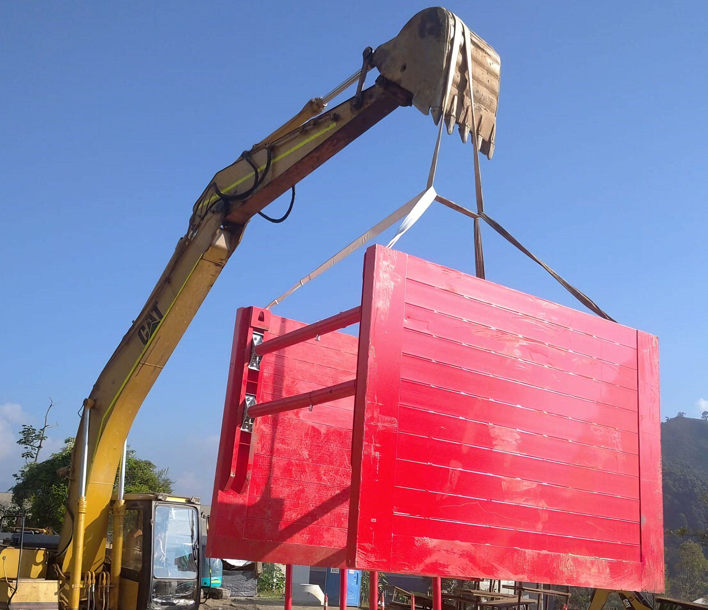
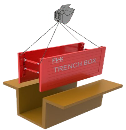
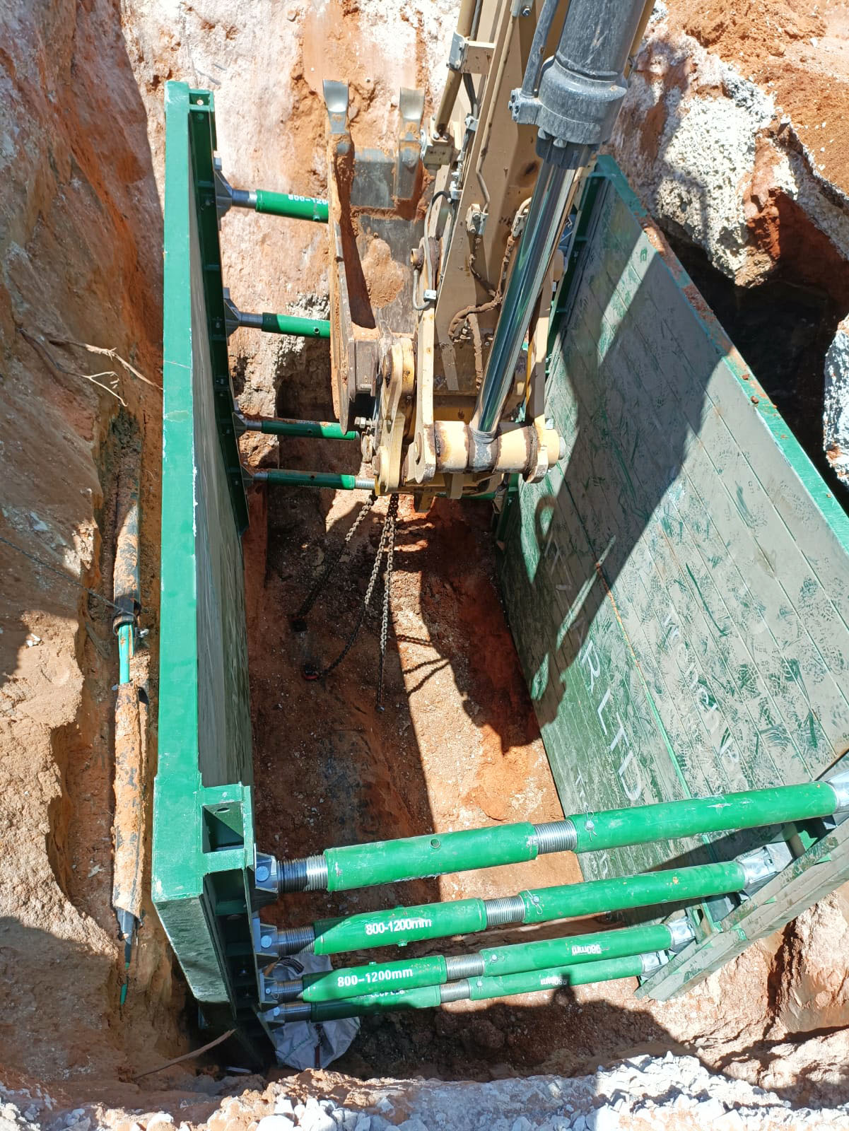
Trench shoring: LG-T100 trench box assembled and lowered into a trench
Every year, trench collapses bury and injure workers who were standing inside an unprotected excavation. A trench box — also called a trench shield — is the most common engineering control against this risk. But choosing the wrong box, or using the right box the wrong way, is still one of the most frequent findings in site safety inspections.
This guide explains, step by step, how contractors and utility companies should select a trench shoring box: which numbers matter, which soil conditions restrict which installation method, and how pipe size drives the geometry of the box you need. The examples use the LG-T100 trench box series, a steel shoring system rated to 5.6 m trench depth, but the selection logic applies to any certified trench box.
What a Trench Box Actually Does
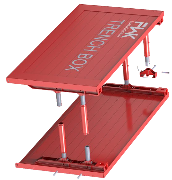
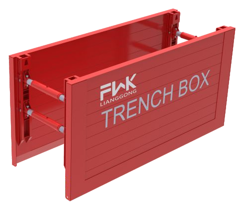
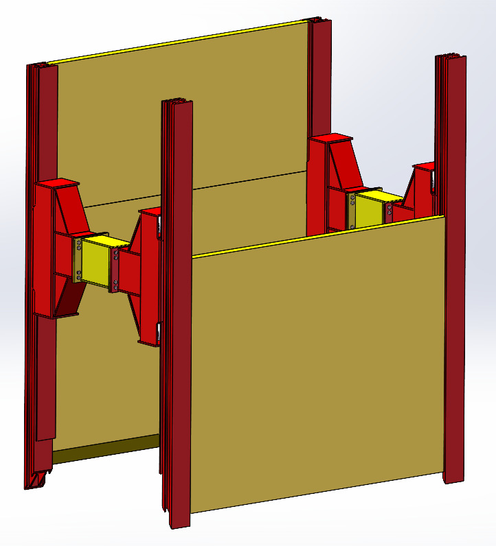
A trench box consists of two steel side panels connected by adjustable spindles (struts). The panels resist the lateral earth pressure acting on the trench walls; the spindles hold the panels apart at a fixed working width so crews can lay pipe between them.
Three points are worth understanding before you compare products:
The box does not prevent collapse — it protects the people inside it. The excavation above and behind the box may still slough; the box creates a protected zone. That is why the top of the shoring should extend at least 5 cm above the surrounding terrain.
The rated load is not the same as the physical size. Two boxes of identical dimensions can have very different allowable earth pressures depending on steel grade and panel thickness. A certified calculation (to EN 13331-1, or GB 50017-based structural checks) is the only reliable source for the rating.
The rating decreases with panel length. Earth pressure bending acts on the panel like a beam: the allowable pressure falls roughly with the square of the unsupported length. Longer panels span more trench, but carry less pressure.
The Four Selection Variables
Variable 1: Trench Depth
Depth drives two decisions: how many panels you stack, and whether a trench box is even the right system.
- Within approximately 4.0m: a single-box or base+top-box configuration is typically the most economical and easiest to handle.
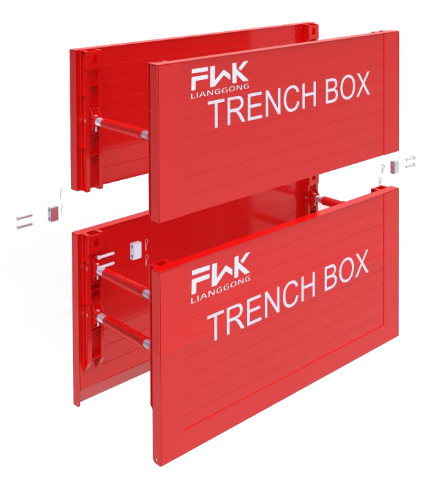
- 4.0–6.0 m: boxes can be stacked (base box + top box connected with box connectors), but only if the soil friction still allows the plates to be pushed down and pulled out. Beyond a certain depth, the friction between plates and soil becomes too large — the box deforms into a parallelogram when raising or lowering, and extraction forces become unsafe. This is the point to switch to a rolling strut (slide rail) system, where each component moves independently and the shoring width never changes.
- Above approximately 6.0 m: engineered slide-rail or sheet-pile solutions.
 |
 |
 |
Practical rule: Trench box up to 4.00 m; rolling strut shoring for greater depths. Stacked trench boxes are theoretically possible to 6.00 m, but verify extraction feasibility case by case.
Variable 2: Soil Conditions — and the Installation Method It Dictates
Soil type does not just affect loads; it decides which installation method is permissible:
Place and adjust method — the box is lowered whole into a pre-excavated trench. Only permitted when all of the following hold:
- The soil is temporarily stable (no significant collapse between excavation start and shoring placement)
- The location is outside the influence zone of buildings, structures, roads, or services at risk
- Settlements are acceptable
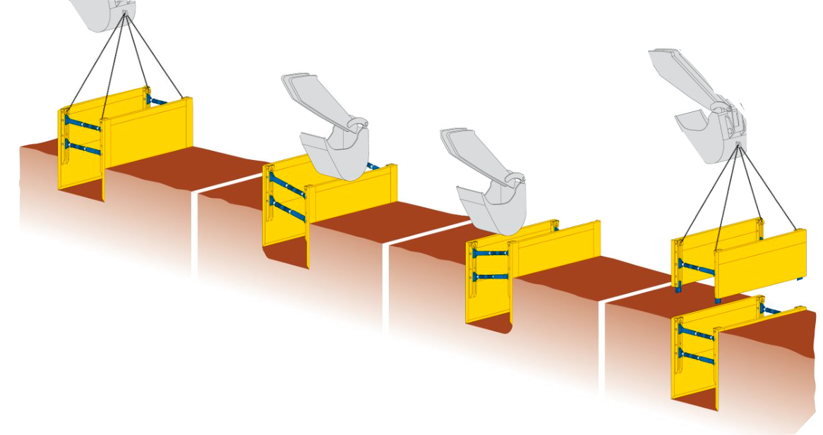
Cut and lower method — used in unstable soils. The box is assembled on the surface, then driven down as excavation alternates beneath it:
- Pre-excavate a maximum of 1.25 m (no longer than one shoring section).
- Lower the spindled base box in, align, push in; fill and compact the void behind the panels.
- Excavate a further 0.50 m and alternately push the two plates down — never force the extension pipes, and never enter the trench during this phase.
- Keep increments ≤ 0.50 m and spindle rotation within ±8°; repeat to final depth.
Also note slope requirements by soil: stable soil may be sloped back to about 53° before additional support is required, whereas unstable soil only to about 34° — past that, a box (or slide rail) is mandatory.
Variable 3: Pipe Diameter and Working Width
The pipe sets the geometry:
- Pipe clearance height (PCH): the clear height between the lower spindle and the panel bottom. It must cover the pipe bed (bedding layer) plus the pipe diameter plus headroom for the laying operation. The LG-T100 offers PCH options of 0.90, 1.10 and 1.30 m depending on model.
- Working width (WW): the clear space between panels — pipe width plus compaction space on both sides. Too narrow and you cannot compact the haunching; too wide and you buy trench width (and backfill volume) you don’t need.
- Plate length (PL): governed by pipe length — the distance between spindles must allow the next pipe section to be joined in the protected zone.
Variable 4: Allowable Earth Pressure (the Number That Actually Protects You)
This is the figure most buyers never check, and the one inspectors should.
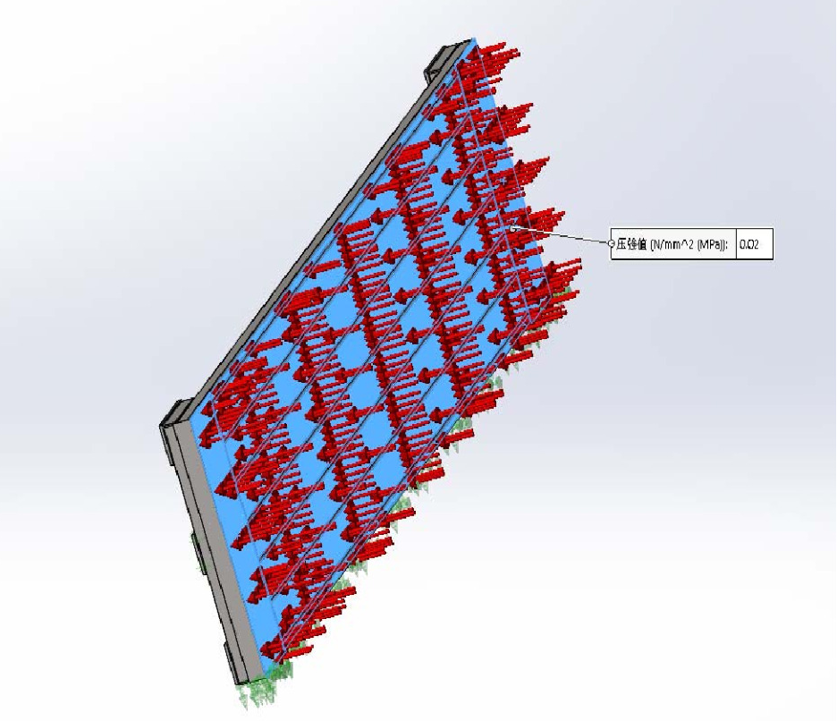
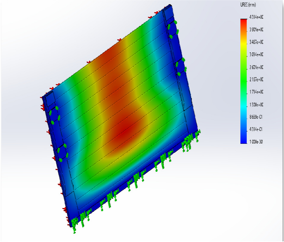
For a certified box, the allowable earth pressure comes from a structural calculation covering both strength and deflection (typically beam deflection limited to L/200), with the smaller value governing. As a worked example, the LG-T100 4000×2010×100 panel in Q355 steel calculates as follows:
- Strength-controlled capacity: 104.75 kN/m² → ×0.8 safety factor = 83.8 kN/m²
- Deflection-controlled capacity: 40 kN/m² → ×0.8 = 32 kN/m²
- Governing allowable load: 32 kN/m² (deflection governs)
Notice the pattern across the series — the same 100 mm panel loses most of its rating as it gets longer:
|
Panel height PH |
Panel length PL |
Allowable earth pressure |
Weight |
|
2.0 m |
3.0 m |
84 kN/m² |
857 kg |
|
2.0 m |
3.5 m |
50 kN/m² |
953 kg |
|
2.0 m |
4.0 m |
32 kN/m² |
1,050 kg |
|
1.4 m |
3.0 m |
71 kN/m² |
605 kg |
|
1.4 m |
4.0 m |
27 kN/m² |
735 kg |
 |
 |
Selection consequence: deep, stiff-soil trenches favor shorter, taller panels; long panels are only safe in shallow or low-pressure conditions. If your geotechnical report suggests high earth pressure at depth, shortening the panel — not thickening the spec sheet — is often the right answer.
Matching the Components: Spindles, Extensions and Intermediate Pipes
The box is a system, and the hydraulics/mechanics of width adjustment matter as much as the panels:
- Spindles (struts) are available in fixed lengths; intermediate extension pipes adjust the working width in steps. For the LG-T100, working width ranges from 1.00–1.40 m up to 4.00–4.40 m using 1–6 intermediate pipes, with safe working loads from 360 kN (narrowest) down to 122 kN (widest). Wider = lower strut load capacity — another trade-off to check.
- Assembly sequence matters for safety: lay the base panel profile-up, insert spring spindle holders secured with 30×175 mm pins, place spindles staggered as required secured with 30×155 mm pins, then lower the second panel onto the spindles from the top.
- A-position rule: extend the bottom strut about 30–50 mm more than the upper one — the shoring must be narrower above and wider below, so the box self-anchors against the trench walls.
- Lifting capacity of attachment points: for the LG-T100, 153 kN per top lifting eye and 49 kN per cutting-edge eye. Use certified chains at a minimum of four points, machinery rated 12–18 t (18–30 t for top elements), and keep loads low during travel.
Quick Selection Table (LG-T100 Example)
| Your condition | Recommended configuration |
| Trench ≤ 2.4 m, stable soil, small pipe | Single base box, 1.4–2.0 m panels, place and adjust |
| Trench ≤ 4.0 m, any typical utility trench | Base + top box (2.0–2.4 m panels), pre-assembled and lowered as one unit |
| Trench 4.0–5.6 m | Stacked boxes only after extraction feasibility check; otherwise rolling strut shoring (LG-S130) |
| Unstable soil / high groundwater influence | Cut and lower method; rolling strut shoring for depth > 4 m |
| Large pipe (needs PCH 1.3 m) | 2.4 m panels with 1.30 m pipe clearance; note the slightly reduced allowable pressure (31–82 kN/m² by length) |
| Narrow urban trench | Minimum working width (1.00–1.40 m, 360 kN strut load) |
| Wide working space (pipes + compaction plant) | 4.00–4.40 m working width — check strut load drops to 122 kN |
Common Selection Mistakes
- Buying by size, not by rating. A 4.0 m panel “fits” a 4 m trench but may only be rated for shallow, low-pressure conditions.
- Using place and adjust in unstable soil. If the trench walls won’t stand between excavation and placement, the method is prohibited — plan for cut and lower or slide rails.
- Ignoring the extraction problem. Stacked boxes to 6 m look fine on paper; friction can make pulling the plates out impossible without damaging them.
- Forgetting the 5 cm rule. The top of the shoring must stand proud of surrounding terrain.
- No structural certificate. Demand the EN 13331-1 (or equivalent) calculation, not just a marketing sheet. Reputable manufacturers supply per-model stress analysis and pre-assembly testing before delivery.
FAQ
Q: What depth is a trench box rated for?
A: The LG-T100 series is rated for trench depths up to 5.6 m, and boxes can be stacked up to 6.0 m where extraction is feasible. Always confirm the depth rating of the specific model certificate, not the product category.
Q: Can I use a trench box in unstable soil?
A:Yes — but only with the cut and lower method (drive the box down as you excavate in ≤0.5 m increments). Place and adjust requires temporarily stable soil.
Q: Trench box or slide rail shoring — which one?
A:Rule of thumb: trench box up to 4.0 m; rolling strut (slide rail) shoring beyond, because each slide rail component moves independently and the shoring width stays constant during pushing/pulling.
Q: How is the allowable earth pressure determined?
A:By structural calculation to EN 13331-1 / steel design codes, checking both strength and deflection (L/200 limit), with a safety factor (typically 0.8) applied, and the smaller of the two values governing.
Q: What excavator size do I need?
A:For the LG-T100: a 12–18 t mobile or crawler excavator for the base element, 18–30 t for the top element.
Q: What steel are trench boxes made of?
A:Structural quality boxes use high-yield steel such as Q355 (σs = 355 MPa) for profiles and plates, with grade-45# steel bolts. Avoid uncertified boxes made from re-rolled scrap.
Plan Your Next Trench Project
Lianggong Formwork (est. 2010, Yancheng, China) manufactures the LG-T100 trench box series (rated to 5.6 m, EN 13331-1-based stress analysis, per-order load calculation reports) and the LG-S130 rolling strut shoring system, with worldwide delivery and OEM/ODM support.
Company: Yancheng Lianggong Formwork Co., Ltd.
Website: https://www.lianggongformwork.com https://www.fwklianggong.com https://lianggongform.com
Email: sales01@lianggongform.com
Tel: +86-18201051212
Address: No.8 Shanghai Road, Jianhu Economic Development Zone, Yancheng City, Jiangsu Province, China
Post time: Oct-30-2026